Architecture
- Architecture
- Introduction
- Assembly Language
- Machine Language
- Programming
- Addressing Modes
Architecture
Introduction
In this chapter we raise the level of abstraction to define the architecture of a computer. The architecture is the programmer’s view of a computer. It is defined by the instruction set (language) and operand locations (registers and memory). Many different architectures exist, such as IA-32, MIPS, SPARC, and PowerPC.
The first step in understanding any computer architecture is to learn its language. The words in a computer’s language are called instructions. The computer’s vocabulary is called the instruction set. All programs running on a computer use the same instruction set. Even complex software applications are eventually compiled into a series of simple instructions such as add, subtract, and jump. Computer instructions indicate both the operation to perform and the operands to use. The operands may come from memory, from registers, or from the instruction itself.
Computer hardware only understands 1’s and 0’s, so instructions are encoded as binary numbers in a format called machine language. Just as we use letters to encode human language, computers use binary numbers to encode machine language. Microprocessors are digital systems that read and execute machine language instructions. However, humans consider reading machine language to be tedious, so we prefer to represent the instructions in a symbolic format, called assembly language.
The instruction sets of different architectures are more like different dialects than different languages. Almost all architectures define basic instructions, such as add, subtract, and jump, that operate on memory or registers.
A computer architecture does not define the underlying hardware implementation. Often, many different hardware implementations of a single architecture exist. For example, Intel and AMD sell various microprocessors belonging to the same IA-32 architecture. They all can run the same programs, but they use different underlying hardware and therefore offer trade-offs in performance, price, and power. Some microprocessors are optimized for high-performance servers, whereas others are optimized for long battery life in laptop computers. The specific arrangement of registers, memories, ALUs, and other building blocks to form a microprocessor is called the microarchitecture. Often, many different microarchitectures exist for a single architecture.
On this page we introduce the MIPS architecture that was first developed by John Hennesssy and his colleagues at Stanford in the 1980’s. MIPS processors are used by, among others, Silicon Graphics, Nintendo, and Cisco. We start by introducing the basic instructions, operand locations, and machine language formats. We then introduce more instructions used in common programming constructs, such as branches, loops, array manipulations, and procedure calls.
Throughout the page we motivate the design of the MIPS architecture using four principles articulated by Patterson and Hennessy:
- simplicity favors regularity
- make the common case fast
- smaller is faster
- good design demands good compromises
Assembly Language
Assembly language is the human-readable representation of the computer’s native language. Each assembly language instruction specifies both the operation to perform and the operands on which to operate. We introduce simple arithmetic instructions and show how these operations are written in assembly language. We then define the MIPS instruction operands: registers, memory, and constants.
Instructions
The most common operation computers perform is addition. The example shows code for adding variables b and c and writing the result to a. The program is shown first in a high-level language, and then rewritten on in MIPS assembly language.
a = b + c;
add a, b, c
The first part of the assembly instruction, add, is called the mnemonic and indicates what operation to perform. The operation is performed on b and c, the source operands, and the result is written to a, the destination operand.
This example shows that subtraction is similar to addition. The instruction format is the same as the add instruction except for the operation specification, sub. This consistent instruction format is an example of the first design principle.
a = b - c;
sub a, b, c
Instructions with a consistent number of operands - in this case, two sources and one destination - are easier to encode and handle in hardware. More complex high-level code translates into multiple MIPS instructions, as shown in this example.
a = b + c - d; // single-line comment
               /* multiple-line
                  comment */
sub t, c, d # t = c - d
add a, b, t # a = b + t
In the high-level language examples, single-line comments begin with // and continue until the end of the line. Multiline comments begin with /* and end with */. In assembly language, only single-line comments are used. They begin with # and continue until the end of the line. The assembly language program in the above example requires a temporary variable, t, to store the intermediate result. Using multiple assembly language instructions to perform more complex operations is an example of the second design principle of computer architecture.
The MIPS instruction set makes the common case fast by including only simple, commonly used instructions. The number of instructions is kept small so that the hardware required to decode the instruction and its operands can be simple, small, and fast. more elaborate operations that are less common are performed using sequences of multiple simple instructions. Thus, MIPS is a reduced instruction set computer (RISC) architecture. Architectures with many complex instructions, such as Intel’s IA-32 architecture, are complex instruction set computers (CISC). For example, IA-32 defines a “string move” instruction that copies a string from one part of memory to another. Such an operation requires many, possibly even hundreds, of simple instructions in a RISC machine. However, the cost of implementing complex instructions in a CISC architecture is added hardware and overhead that slows down the simple instructions.
A RISC architecture minimizes the hardware complexity and the necessary instruction encoding by keeping the set of distinct instructions small. For example, an instruction set with 64 simple instructions would need bits to encode the operation. An instruction set with 256 complex instructions would need bits of encoding per instruction. In a CISC machine, even though the complex instructions may be used only rarely, they add overhead to all instruction, even the simple ones.
Operands: Registers, Memory, and Constants
An instruction operates on operands. But computers operate on 1’s and 0’s, not variable names. The instructions need a physical location from which to retrieve the binary data. Operands can be stored in registers or memory, or they may be constants stored in the instruction itself. Computers use various locations to hold operands, to optimize for speed and data capacity. Operands stored as constants or in registers are accessed quickly, but they hold only a small amount of data. Additional data must be accessed from memory, which is large but slow. MIPS is called a 32-bit architecture because it operates on 32-bit data. The MIPS architecture has been extended to 64 bits in commercial products, but for our purposes we will stick to the 32-bit one.
Registers
Instructions need to access operands quickly so that they can run fast. But operands stored in memory take a long time to retrieve. Therefore, most architectures specify a small number of registers that hold commonly used operands. The MIPS architecture uses 32 registers, called the register set or register file. The fewer the registers. the faster they can be accessed. This is an application of the third design principle.
Looking up information from a small number of relevant books on your desk is a lot faster than searching for the information in the stacks at a library. Likewise, reading data from a mall set of registers is faster than reading it from 10000 registers or a large memory. A small register file is typically built from a small SRAM array. The SRAM array uses a small decoder and bitlines connected to relatively few memory cells, so it has a shorter critical path than a large memory does.
The example shows the add instruction with register operands. MIPS register names are preceded by the $ sign. The variables a, b, and c are arbitrarily placed in $s0, $s1, and $s2. The instruction adds the 32-bit values contained in $s1 and $s2 and writes the 32-bit result to $s0.
a = b + c;
add $s0, $s1, $s2
MIPS generally stores variables in 18 of the 32 registers: $s0 - $s7, and $t0 - $t9. Register names beginning with $s are called saved registers. Following MIPS convention, these registers store variables such as a, b, and c above. Saved registers have special connotations when they are used with procedure calls. Register names beginning with $t are called temporary registers They are used for storing temporary variables.
The example shows MIPS assembly code using a temporary register, $t0, to store the intermediate calculation of c - d.
a = b + c - d;
sub $t0, $s2, $s3
add $s0, $s1, $t0
The Register Set
The MIPS architecture defines 32 registers. Each register has a name and a number ranging from 0 to 31. The table lists the name, number, and use for each register. $0 always contains the value 0 because this constant is so frequently used in computer programs.

Memory
If registers were the only storage space for operands we would be confined to simple programs with no more than 32 variables. However, data can also be stored in memory. When compared to the register file, memory has many data locations, but accessing it takes a longer amount of time. Whereas the register file is small and fast, memory is large and slow. For this reason, commonly used variables are kept in registers. By using a combination of memory and registers, a program can access a large amount of data fairly quickly. As previously described, memories are organized as an array of data words. The MIPS architecture uses 32-bit memory addresses and 32-bit data words.
MIPS uses a byte-addressable memory. That is, each byte in memory has a unique address. However, for explanation purposes only, we first introduce a word-addressable memory and afterwards describe the MIPS byte-addressable memory.
The figure shows a memory array that is word-addressable. That is, each 32-bit data word has a unique 32-bit address. Both the 32-bit word address and the 32-bit data value are written in hexadecimal in the figure. By convention, memory is drawn with low memory addresses toward the bottom and high memory addresses toward the top.

MIPS uses the load word instruction, lw, to read a data word from memory into a register. The example loads memory word 1 into $s3. The lw instruction specifies the effective address in memory as the sum of a base address and an offset. The base address (written in parentheses in the instruction) is a register. The offset is a constant (written before the parentheses). In the example, the base address is $0, which holds the value 0, and the offset is 1, so the lw instruction reads from memory address ($0 + 1) = 1. After the load word instruction is executed, $s3 holds the value 0xF2F1AC07, which is the data value stored at memory address 1 in the above figure.
lw $s3, 1($0)
Similarly, MIPS uses the store word instruction, sw, to write a data word from a register into memory. The example writes the contents of register $s7 into memory word 5. These examples have used $0 as the base address, but remember that any register can be used to supply the base address.
sw $s7, 5($0)
The previous two code examples have shown a computer architecture with a word-addressable memory. The MIPS memory model, however, is byte-addressable, not word-addressable. Each data byte has a unique address. A 32-bit word consists of four 8-bit bytes. So each word address is a multiple of 4, as shown in the figure. Again, both the 32-bit word address and the data value are given in hexadecimal.

The example shows how to read and write words in the MIPS byte-addressable memory. The word address is four times the word number. The MIPS assembly code reads words 0, 2, and 3 and writes words 1, 8, and 100.
1w $s0, 0($0) # read data word 0 (0xABCDEF78) into $s0
1w $s1, 8($0) # read data word 2 (0x01EE2842) into $s1
1w $s2, 0xC($0) # read data word 3 (0x40F30788) into $s2
sw $s3, 4($0) # write $s3 to data word 1
sw $s4, 0x20($0) # write $s4 to data word 8
sw $s5, 400($0) # write $s5 to data word 100
Byte-addressable memories are organized in a big-endian or little-endian fashion, as shown in the figure. In both formats, the most significant byte (MSB) is on the left and the least significant byte (LSB) is on the right. In big-endian machines, bytes are numbered starting with 0 at the big (most significant) end. In little-endian machines, bytes are numbered starting with 0 at the little (least significant) end. Word addresses are the same in both formats and refer to the same four bytes. Only the addresses of bytes within a word differ.
IBMs PowerPC (formerly found in Macintosh computers) uses big-endian addressing. Intel’s IA-32 architecture (found in PCs) uses little-endian addressing. Some MIPS processors are little-endian, and some are big-endian. The choice of endianness is completely arbitrary, but it leads to hassles when sharing data between big-endian and little-endian computers. In examples in this wiki we will use little-endian format whenever byte ordering matters.
In the MIPS architecture, word addresses for lw and sw must be word aligned. That is, the address must be divisible by 4. Thus, the instruction lw $s0, 7($0) is an illegal instruction. Some architectures, like IA-32 for example, allow non-word-aligned data reads and writes, but MIPS requires strict alignment for simplicity. Of course, byte addresses for load byte and store byte, lb and sb need not be word aligned.

Constants/Immediates
Load word and store word, lw and sw, also illustrate the use of constants in MIPS instructions. These constants are called immediates, because their values are immediately available from the instruction and do not require a register or memory access. Add immediate, addi, is another common MIPS instruction that uses an immediate operand. addi adds the immediate specified in the instruction to a value in a register, as shown in the example.
a = a + 4;
b = a - 12;
addi $s0, $s0, 4
addi $s1, $s0, -12
The immediate specified in an instruction is a 16-bit two’s complement number in the range . Subtraction is equivalent to adding a negative number, so, in the interest of simplicity, there is no subi instruction in the MIPS architecture.
Recall that the add and sub instructions use three register operands. But the lw, sw, and addi instructions use two register operands and a constant. Because the instruction formats differ, lw and sw instructions violate design principle 1. However, this issue allows us to introduce the last design principle.
A single instruction format would be simple but not flexible. The MIPS instruction set makes the compromise of supporting three instruction formats. One format, used for instructions such as add and sub, has three register operands. Another, used for instructions such as lw and addi, has two register operands and a 16-bit immediate. A third, to be discussed later, has a 26-bit immediate and no registers.
Machine Language
Assembly language is convenient for humans to read. However, digital circuits understand only 1’s and 0’s. Therefore, a program written in assembly language is translated from mnemonics to a representation using only 1’s and 0’s, called machine language.
MIPS uses 32-bit instructions. Again, simplicity favors regularity, and the most regular choice is to encode all instructions as words that can be stored in memory. Even though some instructions may not require all 32 bits of encoding, variable-length instructions would add too much complexity. Simplicity would also encourage a single instruction format, but, as already mentioned, that is too restrictive. MIPS makes the compromise of defining three instruction formats: R-type, I-type, and J-type. This small number of formats allows for some regularity among all the types, and thus simpler hardware while also accommodating different instruction needs, such as the need to encode large constants in the instruction. R-type instructions operate on three registers. I-type instructions operate on two registers and a 16-bit immediate. J-type instructions (jump) operate on one 26-bit immediate.
R-Type Instructions
The name R-type is short for register-type. R-type instructions use three registers as operands: two as sources, and one as a destination. The figure shows the R-type machine instruction format. The 32-bit instruction has six fields: op, rs, rt, rd, shamt, and funct. Each field is five or six bits, as indicated.
The operation the instruction performs is encoded in the two fields highlighted in blue: op (also called opcode or operation code) and funct (also called the function). All R-type instructions have an opcode of 0. The specific R-type instruction is determined by the funct field. For example, the opcode and funct fields for the add instruction are 0 () and 32 (), respectively. Similarly, the sub instruction has an opcode and funct field of 0 and 34.
The operands are encoded in the three fields: rs, rt, and rd. The first two registers, rs and rt, are the source registers; rd is the destination register. The fields contain the register numbers that were given in the table above.
The fifth field, shamt, is used only in shift operations. In those instructions, the binary value stored in the 5-bit shamt field indicates the amount to shift. For all other R-type instructions, shamt is 0.

The figure shows the machine code for the R-type instructions add and sub. Notice that the destination is the first register in an assembly language instruction, but it is the third register field (rd) in the machine language instruction. For example, the assembly instruction add $s0, $s1, $s2 has rs = $s1, rt = $s2, and rd = $s0.

I-Type Instructions
The name I-type is short for immediate-type. I-type instructions use two register operands and one immediate operand. The figure shows the I-type machine instruction format. The 32-bit instruction has four fields: op, rs, rt, and imm. The first three fields, op, rs, and rt are like those of R-type instructions. The imm field holds the 16-bit immediate.
The operation is determined solely by the opcode, highlighted in blue. The operands are specified in the three fields, rs, rt, and imm. rs and imm are always used as source operands. rt is used as a destination for some instructions (such as addi and lw) but as another source for others (such as sw).

The figure shows several examples of encoding I-type instructions. Recall that negative immediate values are represented using 16-bit two’s complement notation. rt is listed first in the assembly language instruction when it is used as a destination, but it is the second register field in the machine language instruction.
I-type instructions have a 16-bit immediate field, but the immediates are used in 32-bit operations. What should go in the upper half of the 32 bits? For positive immediates, the upper half should be all 0’s, but for negative immediates, the upper half should be all 1’s. Recall that this is called sign extension. An -bit two’s complement number is sign-extended to an -bit number () by copying the sign bit (most significant bit) of the -bit number into all of the upper bits of the -bit number. Sign-extending a two’s complement number does not change its value.
Most MIPS instructions sign-extend the immediate. For example, addi, lw, and sw, do sign extension to support both positive and negative immediates. An exception to this rule is that logical operations (andi, ori, xori) place 0’s in the upper half; this is called zero extension rather than sign extension.

J-Type Instructions
The name J-type is short for jump-type. This format is used only with jump instructions. This instruction format uses a single 26-bit address operand, addr, as shown in the figure. Like other formats, J-type instructions begin with a 6-bit opcode. The remaining bits are used to specify an address, addr. More on J-type instructions below.

Interpreting Machine Language Code
To interpret machine language, one must decipher the fields of each 32-bit instruction word. Different instructions use different formats, but all formats start with a 6-bit opcode field. Thus, the best place to begin is to look at the opcode. If it is 0, the instruction is R-type; otherwise it is I-type or J-type.
The Power of the Stored Program
A program written in machine language is a series of 32-bit numbers representing the instructions. Like other binary numbers, these instructions can be stored in memory. This is called the stored program concept, and it is a key reason why computers are so powerful. Running a different program does not require large amounts of time and effort to reconfigure or rewire hardware; it only requires writing the new program to memory. Instead of dedicated hardware, the stored program offers general purpose computing. In this way, a computer can execute applications ranging from a calculator to a word processor to a video player simply by changing the stored program.
Instructions in a stored program are retrieved, or fetched, from memory and executed by the processor. Even large, complex programs are simplified to a series of memory reads and instruction executions.
The figure shows how machine instructions are stored in memory. In MIPS programs, the instructions are normally stored starting at address 0x00400000. Remember that MIPS memory is byte addressable, so 32-bit (4-byte) instruction addresses advance by 4 bytes, not 1.
To run or execute the stored program, the processor fetches the instructions from memory sequentially. The fetched instructions are then decoded and executed by the digital hardware. The address of the current instruction is kept in a 32-bit register called the program counter (PC). The PC is separate from the 32 registers shown previously.
To execute the code in the figure, the operating system sets the PC to address 0x00400000. The processor reads the instruction at that memory address and executes the instruction 0x8C0A0020. The processor then increments the PC by 4, to 0x00400004, fetches and executes that instruction and repeats.
The architectural state of a microprocessor holds the state of a program. For MIPS, the architectural state consists of the register file and PC. If the operating system saves the architectural state at some point in the program, it can interrupt the program, do something else, then restore the state such that the program continues properly, unaware that it was ever interrupted.

Programming
Software languages such as C or Java are called high-level programming languages, because they are written at a more abstract level than assembly language. Many high-level languages use common software constructs such as arithmetic and logical operations, if/else statements, for and while loops, array indexing, and procedure calls.
Arithmetic/Logical Instructions
The MIPS architecture defines a variety of arithmetic and logical instructions. We introduce these instructions briefly here, because they are necessary to implement higher-level constructs.
Logical Instructions
MIPS logical operations include and, or, xor, and nor. These R-type instructions operate bit-by-bit on two source registers and write the result to the destination register. The figure shows examples of these operations on the two source values 0xFFFF0000 and 0x46A1F0B7. The figure shows the values stored in the destination register, rd, after the instruction executes.
The and instruction is useful for masking bits (i.e., forcing unwanted bits to 0). For example, in the figure, 0xFFFF0000 0x46A1F0B7 = 0x46A10000. The and instruction masks off the bottom two bytes and places the unmasked top two bytes of $s2, 0x46A1, in $s3. Any subset of register bits can be masked.
The or instruction is useful for combining bits from two registers. For example, 0x347A0000 0x000072FC = 0x347A72FC, a combination of the two values.
MIPS does not provide a instruction, but , so the instruction can substitute.
Logical operations can also operate on immediates. These I-type instructions are andi, ori, and xori. nori is not provided, because the same functionality can be easily implemented using the other instructions.

The figure shows examples of the andi, ori and xori instructions. The figure gives the values of the source register and immediate, and the value of the destination register, rt, after the instruction executes. Because these instructions operate on a 32-bit value from a register and a 16-bit immediate, they first zero-extend the immediate to 32 bits.

Shift Instructions
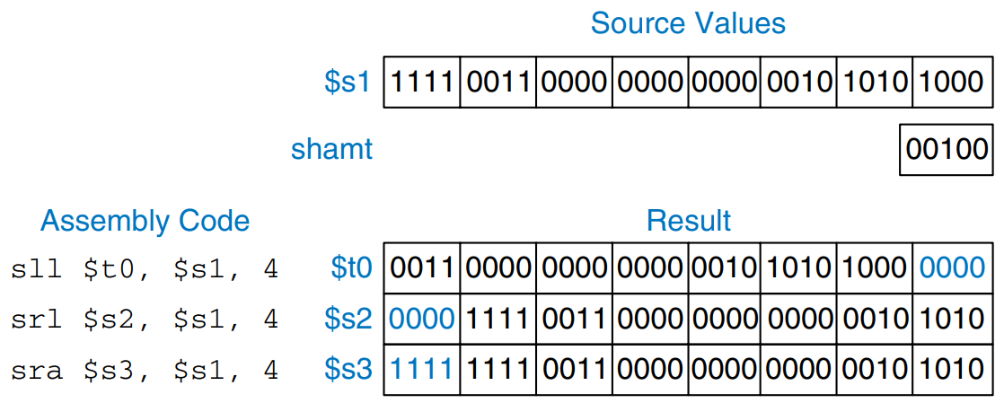
Shift instructions shift the value in a register left or right by up to 31 bits. Shift operations multiply or divide by powers of two. MIPS shift operations are sll (shift left logical), srl (shift right logical), and sra (shift right arithmetic). As discussed previously, left shifts always fill the least significant bits with 0’s. However, right shifts can be either logical (0’s shift into the most significant bits) or arithmetic (the sign bit shifts into the most significant bits). The figure shows the machine code for the R-type instructions sll, srl, and sra. rt (i.e., $s1) holds the 32-bit value to be shifted, and shamt gives the amount by which to shift (4). The shifted result is placed in rd.

The figure shows the register values for the shift instructions sll, srl, and sra. Shifting a value left by is equivalent to multiplying it by . Likewise, arithmetically shifting a value right by is equivalent to dividing it by .
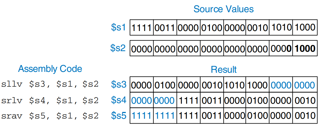
MIPS also has variable-shift instructions: sllv (shift left logical variable), srlv (shift right logical variable), and srav (shift right arithmetic variable). The figure shows the machine code for these instructions.

rt (i.e., $s1) holds the value to be shifted, and the five least significant bits of rs (i.e., $s2) give the amount to shift. The shifted result is placed in rd as before. The shamt field is ignored and should be all 0’s. The figure shows register values for each type of variable-shift instruction.
Generating Constants
The addi instruction is helpful for assigning 16-bit constants, as shown in the example.
int a = 0x4f3c;
addi $s0, $0, 0x4f3c
To assign 32-bit constants, use a load upper immediate instruction (lui) followed by an or immediate (ori) instruction, as shown in the example.
int a = 0x6d5e4f3c;
lui $s0, 0x6d5e
ori $s0, $s0, 0x4f3c
lui loads a 16-bit immediate into the upper half of a register and sets the lower half to 0. As mentioned earlier, ori merges a 16-bit immediate into the lower half.
Multiplication and Division Instructions
Multiplication and division are somewhat different from other arithmetic operations. Multiplying two 32-bit numbers produces a 64-bit product. Dividing two 32-bit numbers produces a 32-bit quotient and a 32-bit remainder.
The MIPS architecture has two special-purpose registers, hi and lo, which are used to hold the results of multiplication and division. mult $s0, $s1 multiplies the values in $s0 and $s1. The 32 most significant bits are placed in hi and the 32 least significant bits are placed in lo. Similarly, div $s0, $s1 computes $s0/$s1. The quotient is placed in lo and the remained is placed in hi.
Branching
An advantage of a computer over a calculator is its ability to make decisions. A computer performs different tasks depending on the input. For example, if/else statements, case statements, while loops and for loops all conditionally execute code depending on some test. To sequentially execute instructions, the program counter increments by 4 after each instruction. Branch instructions modify the program counter to skip over sections of code or to go back to repeat previous code. Conditional branch instructions perform a test and branch only if the test is TRUE. Unconditional branch instructions, called jumps, always branch.
Conditional Branches
The MIPS instruction set has two conditional branch instructions: branch if equal (beq) and branch if not equal (bne). beq branches when the values in two registers are equal, and bne branches when they are not equal. The example illustrates the use of beq. Note that branches are written as beq $rs, $rt, imm, where $rs is the first source register. This order is reversed from most I-type instructions.
  addi $s0, $0, 4
  addi $s1, $0, 1
  sll $s1, $s1, 2
  beq $s0, $s1, target
  addi $s1, $s1, 1
  sub $s1, $s1, $s0

target:
  add $s1, $s1, $s0
When the above program reaches the branch if equal instruction, the value in $s0 is equal to the value in $s1, so the branch is taken. That is, the next instruction executed is the add instruction just after the label called target. The two instructions directly after the branch and before the label are not executed.
Assembly code uses labels to indicate instruction locations in the program. When the assembly code is translated into machine code, these labels are translated into instruction addresses. MIPS assembly labels are followed by a (:) and cannot use reserved words such as instruction mnemonics. Most programmers indent their instructions but not the labels, to help make labels stand out.
The example shows an example using the branch if not equal instruction (bne). In this case, the branch is not taken because $s0 is equal to $s1, and the code continues to execute directly after the bne instruction. All instructions in this code snippet are executed.
  addi $s0, $0, 4
  addi $s1, $0, 1
  s11 $s1, $s1, 2
  bne $s0, $s1, target
  addi $s1, $s1, 1
  sub $s1, $s1, $s0
target:
  add $s1, $s1, $s0
Jump
A program can unconditionally branch, or jump, using the three types of jump instructions: jump (j), jump and link (jal), and jump register (jr). Jump jumps directly to the instruction at the specified label. Jump and link is similar to jummp but is used by procedures to save a return address. Jump register jumps to the address held in a register. The example shows the use of the jump instruction.
  addi $s0, $0, 4
  addi $s1, $0, 1
  j target
  addi $s1, $s1, 1
  sub $s1, $s1, $s0
target:
  add $s1, $s1, $s0
This example shows the use of the jump register instruction. Instruction addresses are given to the left of each instruction.
0x00002000 addi $s0, $0, 0x2010  # $s0 = 0x2010
0x00002004 jr $s0                # jump to 0x00002010
0x00002008 addi $s1, $0, 1       # not executed
0x0000200c sra $s1, $s1, 2       # not executed
0x00002010 lw $s3, 44 ($s1)      # executed after jr instruction
Conditional Statements
if statements, if/else statements, and case statements are conditional statements commonly used by high-level languages. They each conditionally execute a block of code consisting of one or more instructions. This section shows how to translate these high-level constructs into MIPS assembly language.
If Statements
An if statement executes a block of code, the if block, only when a condition is met. The example shows how to translate an if statement into MIPS assembly code.
if (i == j) {
    f = g + h;
}

f = f - 1;
  bne $s3, $s4, L1
  add $s0, $s1, $s2
L1:
  sub $s0, $s0, $s3
The assembly code for the if statement tests the opposite condition of the one in the high-level code. The high-level code tests for i == j, and the assembly code tests for i != j. The bne instruction branches when i != j. Otherwise, i == j, the branch is not taken and the if block i executed as desired.
If/Else Statements
if/else statements execute one of two blocks of code depending on a condition. When the condition in the if statement is met, the if block is executed. Otherwise, the else block is executed. The examples shows an example if/else statement.
if (i == j) {
    f = g + h;
} else {
    f = f - i;
}
  bne $s3, $s4, else
  add $s0, $s1, $s2
  j L2
else:
  sub $s0, $s0, $s3
L2:
Like if statements, if/else assembly code tests the opposite condition of the one in the high-level code. The above code tests for i == j. The assembly code tests for the opposite condition (i != j). If that opposite condition is TRUE, bne skips the if block and executes the else block. Otherwise, the if block executes and finishes with a jump instruction to jump past the else block.
Switch/Case Statements
switch/case statements execute one of several blocks of code depending on the conditions. If no conditions are met, the default block is executed. A case statement is equivalent to a series of nested if/else statements. The example shows two high-level code snippets with the same functionality: they calculate the fee for an ATM, as defined by amount. The MIPS assembly implementation is the same for both high-level code snippets.
switch (amount) {
    case 20: fee = 2; break;
    case 50: fee = 3; break;
    case 100: fee = 5; break;
    default: fee = 0;
}

// equivalent function using if/else statements
if (amount == 20) fee = 2;
else if (amount == 50) fee = 3;
else if (amount == 100) fee = 5;
else fee = 0;
case20:
  addi $t0, $0, 20
  bne $s0, $t0, case50
  addi $s1, $0, 2
  j done
case50:
  addi $t0, $0, 50
  bne $s0, $t0, case100
  addi $s1, $0, 3
  j done
case100:
  addi $t0, $0, 100
  bne $s0, $t0, default
  addi $s1, $0, 5
  j done
default:
  add $s1, $0, $0
done:
Loops
Loops repeatedly execute a block of code depending on a condition. for loops and while loops are common loop constructs used by high-level languages. This section shows how to translate them into MIPS assembly language.
While Loops
while loops repeatedly execute a block of code until a condition is not met. The while loop in the example determines the value of x such that . It executes seven times, until pow = 128.
int pow = 1;
int x = 0;

while (pow != 128) {
    pow = pow * 2;
    x = x + 1;
}
  addi $s0, $0, 1
  addi $s1, $0, 0
  addi $t0, $0, 128
while:
  beq $s0, $t0, done
  sll $s0, $s0, 1
  addi $s1, $s1, 1
  j while
done:
Like if/else statements, the assembly code for the while loop tests the opposite condition of the one given in the high-level code. If that opposite condition is TRUE, the while loop is finished.
The above while loop compares pow to 128 and exits the loop if it is equal. Otherwise, it doubles pow (using a left shift), increments x and jumps back to the start of the while loop.
For Loops
for loops, like while loops, repeatedly execute a block of code until a condition is not met. However, for loops add support for a loop variable, which typically keeps track of the number of loop executions. A general format of the for loop is
for (initialization; condition; loop operation)
The initialization code executes before the for loop begins, The condition is tested at the beginning of each loop. If the condition is not met, the loop exits. The loop operation executes at the end of each loop.
The example adds the numbers from 0 to 9. The loop variable, i, is initialized to 0 and is incremented at the end of each loop iteration. At the beginning of each iteration, the for loop executes only when i is not equal to 10. Otherwise, the loop is finished. In this case, the for loop executes 10 times. for loops can be implemented using a while loop, but the for loop is often convenient.
int sum = 0;

for (int i = 0; i != 10; i = i + 1) {
    sum = sum + 1;
}

// equivalent to the following while loop
int sum = 0;
int i = 0;
while (i != 10) {
    sum = sum + i;
    i = i + 1;
}
  add $s1, $0, $0
  addi $s0, $0, 0
  addi $t0, $0, 10
for:
  beq $s0, $t0, done
  add $s1, $s1, $s0
  addi $s0, $s0, 1
  j for
done:
Magnitude Comparison
So far, the examples have used beq and bne to perform equality or inequality comparisons and branches. MIPS provides the set less than instruction, slt, for magnitude comparison. slt sets rd to 1 when rs < rt. Otherwise, rd is 0.
The following high-level code adds the powers of 2 from 1 to 100.
int sum = 0;
for (int i = 1; i < 101; i = i * 2) {
    sum = sum + i;
}
  addi $s1, $0, 0
  addi $s0, $0, 1
  addi $t0, $0, 101
loop:
  slt $t1, $s0, $t0
  beq $t1, $0, done
  add $s1, $s1, $s0
  sll $s0, $s0, 1
  j loop
done:
Arrays
Arrays are useful for accessing large amounts of similar data. An array is organized as sequential data addresses in memory. Each array element is identified by a number called its index. The number of elements in the array is called the size of the array. This section shows how to access array elements in memory.
Array Indexing
The figure shows an array of five integers stored in memory. The index ranges from 0 to 4. In this case, the array is stored in a processor’s main memory starting at base address 0x10007000. The base address gives the address of the first array element, array[0].
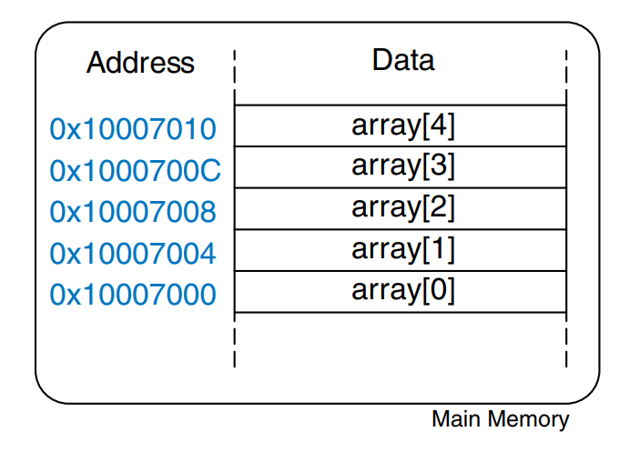
The example multiplies the first two elements in array by 8 and stores them back in the array.
int array [5];

array[0] = array[0] * 8;
array[1] = array[1] * 8;
lui $s0, 0x1000
ori $s0, $s0, 0x7000
lw $t1, 0($s0)
sll $t1, $t1, 3
sw $t1, 0($s0)
lw $t1, 4($s0)
sll $t1, $t1, 3
sw $t1, 4($s0)
The first step in accessing an array element is to load the base address of the array into a register. The example loads the base address into $s0. Recall that the load upper immediate (lui) and or immediate (ori) instructions can be used to load a 32-bit constant into a register.
The example also illustrates why lw takes a base address and an offset. The base address points to the start of the array. The offset can be used to access subsequent elements of the array.
One might have notices that the code for manipulating each of the array elements in the example is essentially the same except for the index. When accessing all of the elements in a large array, this would become terribly inefficient.
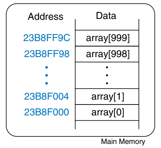
This example uses a for loop to multiply all of the elements of a 1000-element array by 8, which is stored at a base address of 0x23B8F000.
int array[1000];

for (int i = 0; i < 1000; i = i + 1) {
    array[i] = array[i] * 8;
}
  lui $s0, 0x23B8
  ori $s0, $s0, 0xF000
  addi $s1, $0
  addi $t2, $0, 1000
loop:
  slt $t0, $s1, $t2
  beq $t0, $0, done
  sll $t0, $s1, 2
  add $t0, $t0, $s0
  lw $t1, 0($t0)
  sll $t1, $t1, 3
  sw $t1, 0($t0)
  addi $s1, $s1, 1
  j loop
done:
The figure shows the 1000-element array in memory. The index into the array is now a variable rather than a constant, so we cannot take advantage of the immediate offset in lw. Instead, we compute the address of the i-th element and store it in $t0. Remember that each array element is a word but that memory is byte addressed, so the offset from the base address is 4 * i. Shifting left by 2 is a convenient way to multiply by 4 in MIPS assembly language.
Bytes and Characters
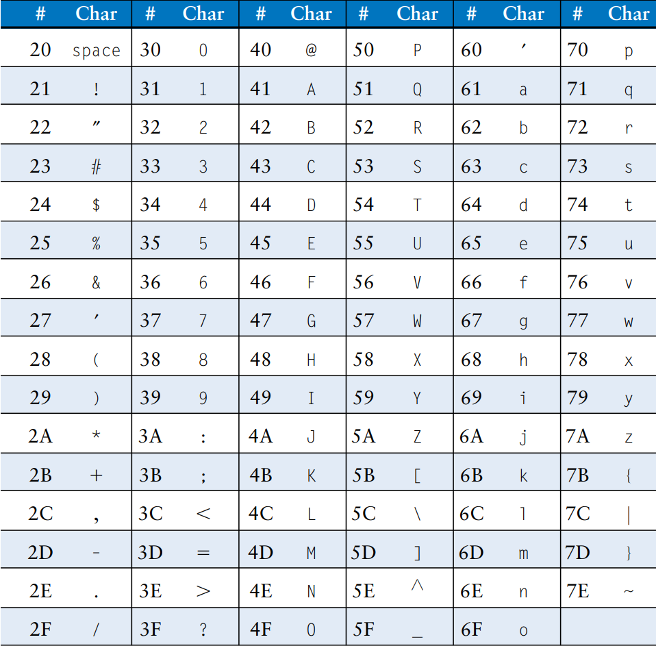
Numbers in the range can be stored in a single byte rather than an entire word. Because there are much fewer than 256 characters on an English language keyboard, English characters are often represented by bytes. The C language uses the type char to represent a byte or character. Early computers lacked a standard mapping between bytes and English characters, so exchanging text between computers was difficult. In 1963, the American Standards Association published the American Standard Code for Information Interchange (ASCII), which assigns each text character a unique byte value. The table shows these character encodings for printable characters. The ASCII values are given in hexadecimal. Lower-case and upper-case letters differ by 0x20 (32).
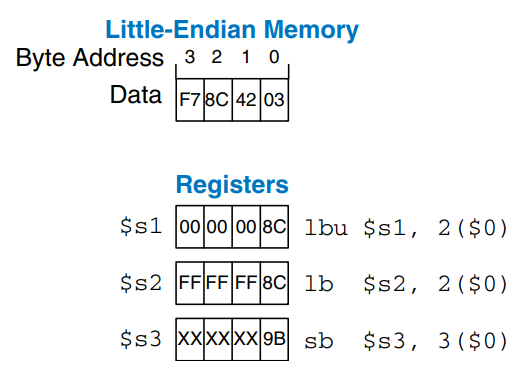
MIPS provides load byte and store byte instructions to manipulate bytes or characters of data: load byte unsigned (lbu), load byte (lb) and store byte (sb). All three are illustrated in the figure.
Load byte unsigned zero-extends the byte, and load byte sign-extends the byte to fill the entire 32-bit register. Store byte stores the least significant byte of the 32-bit register into the specified byte address in memory. In the figure, lbu loads the byte at memory address 2 into the least significant byte of $s1 and fills the remaining register bits with 0. lb loads the sign-extended byte at memory address 2 into $s2. sb stores the least significant byte of $s3 into memory byte 3; it replaces 0xF7 with 0x9B. The more significant bytes of $s3 are ignored.
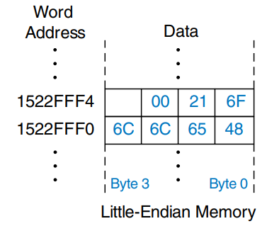
A series of characters is called a string. Strings have a variable length, so programming languages must provide a way to determine the length or end of the string. In C, the null character 0x00 signifies the end of a string. The figure shows the string “Hello!” stored in memory. The string is seven bytes long. The first character of the string is stored at the lowest byte address.
Procedure Calls
High-level languages often use procedures (also called functions) to reuse frequently accessed code and to make a program more readable. Procedures have inputs, called arguments, and an output, called the return value. Procedures should calculate the return value and cause no other unintended side effects.
When one procedure calls another, the calling procedure, the caller, and the called procedure, the callee, must agree on where to put the arguments and the return value. In MIPS, the caller conventionally places up to four arguments in registers$a0 - $a3 before making the procedure call, and the callee places the return value in registers $v0 - ävv1 before finishing. By following this convention, both procedures know where to find the arguments and return value, even if the caller and callee were written by different people.
The callee must not interfere with the function of the caller. Briefly, this means that the callee must know where to return to after it completes and it must not trample on any registers or memory needed by the caller. The caller stores the return address in $ra at the same time it jumps to the callee using the jump and link instruction (jal). The callee must not overwrite any architectural state or memory that the caller is depending on. Specifically, the callee must leave the saved registers, $s0 - $s7, $ra, and the stack, a portion of memory used for temporary variables, unmodified.
Procedure Calls and Returns
MIPS uses the jump and link instruction (jal) to call a procedure and the jump register instruction (jr) to return from a procedure. The example shows the main procedure calling the simple procedure. main is the caller, and simple is the callee. The simple procedure is called with no input arguments and generates no return value; it simply returns to the caller.
int main() {
    simple();
    ...
}

void simple() {
    return;
}
main: jal simple
      ...

simple: jr $ra
Jump and link and jump register are the two essential instructions needed for a procedure call. jal performs two functions: it stores the address of the next instruction (the instruction after jal) in the return address register ($ra) and it jumps to the target instruction.
Input Arguments and Return Values
The procedure above is not very useful, because it receives no input from the calling procedure and returns no output. By MIPS convention, procedures use $a0 - $a3 for input arguments and $v0 - $v1 for the return value. In the example, the procedure diffofsums is called with four arguments and returns one result.
int main() {
    int y;
    ...
    y = diffofsums(2, 3, 4, 5);
    ...
}

int diffofsums(int f, int g, int h, int i) {
    int result = (f + g) - (h + i);
    return result;
}
main:
  ...
  addi $a0, $0, 2
  addi $a1, $0, 3
  addi $a2, $0, 4
  addi $a3, $0, 5
  jal diffofsums
  add $s0, $v0, $0

diffofsums:
  add $t0, $a0, $a1
  add $t1, $a2, $a3
  sub $s0, $t0, $t1
  add $v0, $s0, $0
  jr $ra
According to MIPS convention, the calling procedure, main, places the procedure arguments, from left to right, into the input registers, $a0 - $a3. The called procedure, diffofsums, stores the return value in the return register, $v0.
A procedure that returns a 64-bit value, such as a double-precision floating point number, uses both return registers, $v0 and $v1. When a procedure with more than four arguments is called, the additional input arguments are placed on the stack.
The Stack
The stack is memory that is used to save local variables within a procedure. The stack expands (uses more memory) as the processor needs more scratch space and contracts (uses less memory) when the processor no longer needs the variables stored there. The stack is a last-in-first-out (LIFO) queue. Like a stack of dishes, the last item pushed onto the stack is the first one that can be popped off. Each procedure may allocate stack space but must deallocate it before returning. The top of the stack, is the most recently allocated space. Whereas a stack of dishes grows up in space, the MIPS stack grows down in memory. The stack expands to lower memory addresses when a program needs more scratch space.
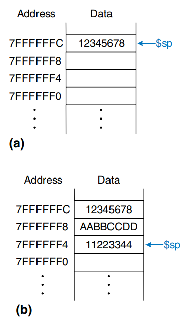
The figure shows a picture of the stack. The stack pointer, $sp, is a special MIPS register that points to the top of the stack. A pointer is a fancy name for a memory address. It points to (gives the address of) data.
The stack pointer ($sp) starts at a high memory address and decrements to expand as needed. b) shows the stack expanding to allow two more data words of temporary storage. To do so, $sp decrements by 8.
One of the important uses of the stack is to save and restore registers that are used by a procedure. Recall that a procedure should calculate a return value but have no other unintended side effects. In particular, it should not modify any registers besides the one containing the return value, $v0. The diffofsums procedure in the above example violate this rule because it modifies $t0, $t1 and $s0. If main had been using these registers before the call to diffofsums, the contents of these registers would have been corrupted by the procedure call.
To solve this problem, a procedure saves registers on the stack before it modifies them, then restores them from the stack before it returns. Specifically, it performs the following steps.
- Makes space on the stack to store the values of one or more registers
- Stores the values of the registers on the stack
- Executes the procedure using the registers
- Restores the original values of the registers from the stack
- Deallocates space on the stack
The example shows an improved version of diffofsums that saves and restores $t0, $t1, and $s0.
diffofsums:
  addi $sp, $sp, 12
  sw $s0, 8($sp)
  sw $t0, 4($sp)
  sw $t1, 0($sp)
  add $t0, $a0, $a1
  add $t1, $a2, $a3
  sub $s0, $t0, $t1
  add $v0, $s0, $0
  lw $t1, 0($sp)
  lw $t0, 4($sp)
  lw $s0, 8($sp)
  addi $sp, $sp, 12
  jr $ra
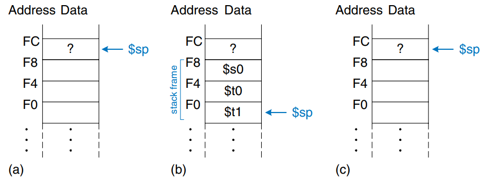
The figure shows the stack before, during, and after a call to the diffofsums procedure. diffofsums makes room for three words on the stack by decrementing the stack pointer by 12. It then stores the current values of $s0, $t0 and $s1 in the newly allocated space. It executes the rest of the procedure, changing the values in these three registers. At the end of the procedure, diffofsums restores the values of $s0, $t0, and $t1 from the stack, deallocates its stack space, and returns. When the procedure returns, $v0 holds the result, but there are no other side effects: $s0, $t0, $t1 and $sp have the same values as they did before the procedure call.
The stack space that a procedure allocates for itself is called its stack frame. diffofsums stack frame is three words deep. The principle of modularity tells us that each procedure should access only its own stack frame, not the frames belonging to other procedures.
Preserved Registers
The above example assumes that temporary registers $t0 and $t1 must be saved and restored. If the calling procedure does not use those registers, the effort to save and restore them is wasted. To avoid this waste, MIPS divides registers into preserved and nonpreserved categories. The preserved registers include $s0 - $s7 (hence their name, saved). The nonpreserved registers include $t0 - $t9 (hence their name, temporary). A procedure must save and restore any of the preserved registers that it wishes to use, but it can change the nonpreserved registers freely.
The example shows a further improved version of diffofsums that saves only $s0 on the stack. $t0 and $t1 are nonpreserved registers, so they need not be saved.
diffofsums:
  addi $sp, $sp, 4
  sw $s0, 0($sp)
  add $t0, $a0, $a1
  add $t1, $a2, $a3
  sub $s0, $t0, $t1
  add $v0, $s0, $0
  lw $s0, 0($sp)
  addi $sp, $sp, 4
  jr $ra
Remember that when one procedure calls another, the former is the caller and the latter is the callee. The callee must save and restore any preserved register that it wishes to use. The callee may change any of the nonpreserved registers. Hence, if the caller is holding active data in a nonpreserved register, the caller needs to save that nonpreserved register before making the procedure call and then needs to restore it afterward. For these reasons, preserved registers are also called callee-save, and nonpreserved registers are also called caller-save.
The table summarizes which registers are preserved. $s0 - $s7 are generally used to hold local variables within a procedure, so they must be saved. $ra must also be saved, so that the procedure knows where to return. $t0 - $t9 are used to hold temporary results before they are assigned to local variables. These calculations typically complete before a procedure call is made, so they are not preserved, and it is rare that the caller needs to save them. $a0 - $a3 are often overwritten in the process of calling a procedure. hence, they must be saved by the caller if the caller depends on any of its own arguments after a called procedure returns. $v0 - $v1 certainly should not be preserved, because the callee returns its result in these registers.
The stack above the stack pointer is automatically preserved as long as the callee does not write to memory addresses above $sp. In this way, it does not modify the stack frame of any other procedures. The stack pointer itself is preserved, because the callee deallocates its stack frame before returning by adding back the same amount that it subtracted from$sp at the beginning of the procedure.

Recursive Procedure Calls
A procedure that does not call others is called a leaf procedure; an example is diffofsums. A procedure that does call others is called a nonleaf procedure. As mentioned earlier, nonleaf procedures are somewhat more complicated because they may need to save nonpreserved registers on the stack before they call another procedure, and then restore those registers afterward. Specifically, the caller saves and nonpreserved registers that are needed after the call. The callee saves any of the preserved registers that it intends to modify.
A recursive procedure is a nonleaf procedure that calls itself. The factorial function can be written as a recursive procedure call. Recall that , The factorial function can be rewritten recursively as . The factorial of 1 is simply 1. The example shows the factorial function written as a recursive procedure.
int factorial(int n) {
    if (n <= 1) {
        return 1;
    } else {
        return n * factorial(n - 1);
    }
}
factorial:
  addi $sp, $sp, -8
  sw $a0, 4($sp)
  sw $ra, 0($sp)
  addi $t0, $0, 2
  slt $t0, $a0, $t0
  beq $t0, $0, else
  addi $v0, $0, 1
  addi $sp, $sp, 8
  jr $ra
else:
  addi $a0, $a0, -1
  jal factorial
  lw $ra, 0($sp)
  lw $a0, 4($sp)
  addi $sp, $sp, 8
  mul $v0, $a0, $v0
  jr $ra
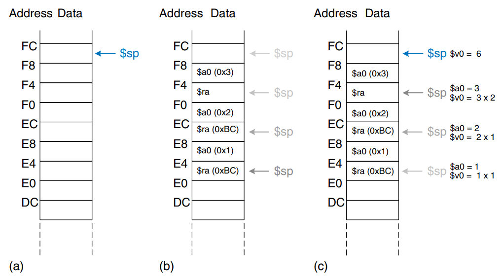
The factorial procedure might modify $a0 and $ra, so it saves them on the stack. It then checks whether n < 2. If so, it puts the return value of 1 in $v0, restores the stack pointer, and returns to the caller. It does not have to reload $ra and $a0 in this case, because they were never modified. If n > 1, the procedure recursively calls factorial(n - 1). If then restores the value of n and the return address $ra from the stack, performs the multiplication, and returns this result. The multiply instruction multiplies $a0 and $v0 and places the result in $v0.
The figure shows the stack when executing factorial(3).
Additional Arguments and Local Variables
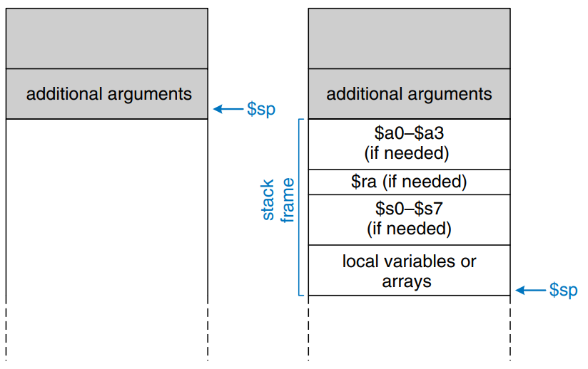
Procedures may have more than four input arguments and local variables. The stack is used to store these temporary values. By MIPS convention, if a procedure has more than four arguments, the first four are passed in the argument registers as usual. Additional arguments are passed on the stack, just above $sp. The caller must expand its stack to make room for the additional arguments. Figure a) shows the caller’s stack for calling a procedure with more than four arguments.
A procedure can also declare local variables or arrays. Local variables are declared within a procedure and can be accessed only within that procedure. Local variable are stored in $s0 - $s7; if there are too many local variables, they can also be stored in the procedure’s stack frame. In particular, local arrays are stored on the stack.
Figure b) shows the organization of the callee’s stack frame. The frame holds the procedure’s own arguments, the return address, and any of the saved registers that the procedure will modify. It also holds local arrays and any excess local variables. If the callee has more than four arguments, it finds them in the caller’s stack frame. Accessing additional input arguments is the one exception in which a procedure can access stack data not in its own stack frame.
Addressing Modes
MIPS uses five addressing modes: register-only, immediate, base, PC-relative, and pseudo-direct. The first three modes define modes of reading and writing operands. The last two define modes of writing the program counter.
Register-Only Addressing
Register-only addressing uses registers for all source and destination operands. All R-type instructions use register-only addressing.
Immediate Addressing
Immediate addressing uses the 16-bit immediate along with registers as operands. Some I-type instructions, such as add immediate and load upper immediate, use immediate addressing.
Base Addressing
Memory access instructions, such as load word and store word, use base addressing. The effective address of the memory operand is found by adding the base address in register rs to the sign-extended 16-bit offset found in the immediate field.
PC-relative Addressing
Conditional branch instructions use PC-relative addressing to specify the new value of the PC if the branch is taken. The signed offset in the immediate field is added to the PC to obtain the new PC; hence, the branch destination address is said to be relative to the current PC. The example shows part of the factorial procedure from earlier.
  beq $t0, $0, else
  addi $v0, $0, 1
  addi $sp, $sp, 8
  jr $ra
else:
  addi $a0, $a0, -1
  jal factorial
The figure shows the machine code for the beq instruction. The branch target address (BTA) is the address of the next instruction to execute if the branch is taken. The beq instruction in the figure has a BTA of 0xB4, the instruction address of the else label.

Pseudo-Direct Addressing
In direct addressing, an address is specified in the instruction. The jump instructions, j and jal, ideally would use direct addressing to specify a 32-bit jump target address (JTA) to indicate the instruction address to execute next.
Unfortunately, the J-type instruction encoding does not have enough bits to specify a full 32-bit JTA. Six bits of the instruction are used for the opcode, so only 32 bits are left to encode the JTA. Fortunately, the two last significant bits, , should always be 0, because instructions are word aligned. The next 26 bits, , are taken from the addr field of the instruction. The four most significant bits, , are obtained from the four most significant bits of PC+4. This addressing mode is called pseudo-direct.
The example illustrates a jal instruction using pseudo-direct addressing.
  jal sum
sum:
  add $v0, $a0, $a1
The figure shows the machine code for the instruction. The top four bits and bottom two bits of the JTA are discarded. The remaining bits are stored in the 26-bit address field.
The processor calculates the JTA from the J-type instruction by appending two 0’s and pepending the four most significant bits of PC+4 to the 26-bit address field.
Because the four most significant bits of the JTA are taken from PC+4, the jump range is limited. All J-type instructions, j and jal, use pseudo-direct addressing.
Note that the jump register instruction, jr, is not a J-type instruction. It is an R-type instruction that jumps to the 32-bit value held in register rs.

Compiling, Assembling, and Loading
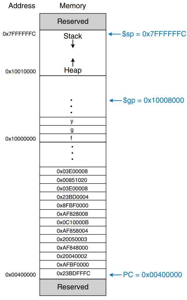
We introduce the MIPS memory map, which defines where code, data, and stack memory are located.
The Memory Map
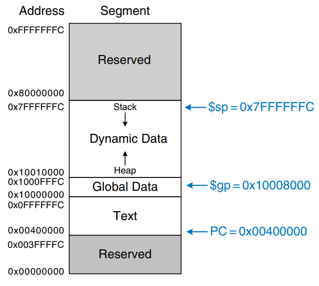
With 32-bit addresses, the MIPS address space spans bytes = 4 gigabytes (GB). Word addresses are divisible by 4 and range from 0 to 0xFFFFFFFC. The figure shows the MIPS memory map. The MIPS architecture divides the address space into four parts or segments: the text segment, global data segment, dynamic data segment, and reserved segments.
The Text Segment
The text segment stores the machine language program. It is large enough to accommodate almost 256 MB of code. Note that the four most significant bits of the address in the text space are all 0, so the j instruction can directly jump to any address in the program.
The Global Data Segment
The global data segment stores global variables that, in contrast to local variables, can be seen by all procedures in a program. Global variables are defined at start-up, before the program begins executing. These variables are declared outside the main procedure in a C program and can be accessed by any procedure. The global data segment is large enough to store 64 KB of global variables.
Global variables are accessed using the global pointer ($gp), which is initialized to 0x100008000. Unlike the stack pointer ($sp), $gp does not change during program execution. Any global variable can be accessed with a 16-bit positive or negative offset from $gp. The offset is known at assembly time, so the variables can be efficiently accessed using base addressing mode with constant offsets.
The Dynamic Data Segment
The dynamic data segment holds the stack and the heap. The data in this segment are not known at start-up but are dynamically allocated and deallocated throughout the execution of the program. this is the largest segment of memory, spanning almost 2 GB of the address space.
As discussed previously, the stack is used to save and restore registers used by procedure and to hold local variables such as arrays. The stack grows downward from the top of the dynamic data segment (0x7FFFFFFC) and is accessed in last-in-first-out (LIFO) order.
The heap stores data that is allocated by the program during runtime. In C, memory allocations are made by the malloc function; in C++ and Java, new is used to allocate memory. Like a heap of clothes on a dorm room floor, heap data can be used and discarded in any order. The heap grows upward from the bottom of the dynamic data segment.
If the stack and heap ever grow into each other, the program’s data can become corrupted. The memory allocator tries to ensure that this never happens by returning an out-of-memory error if there is insufficient space to allocate more dynamic data.
The Reserved Segments
The reserved segments are used by the operating system and cannot directly be used by the program. Part of the reserved memory is used for interrupts and for memory-mapped I/O.
Translating and Starting a Program
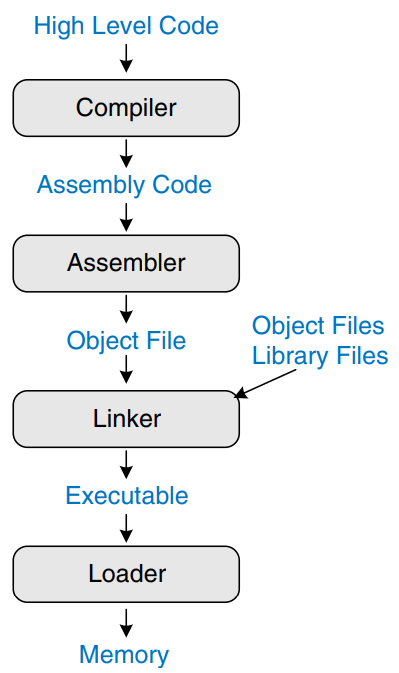
The figure shows the steps required to translate a program from a high-level language into machine language and to start executing that program. First, the high-level assembly code is compiled into assembly code. The assembly code is assembled into machine code in an object file. The linker combines the machine code with object code from libraries and other files to produce an entire executable program. In practice, most compilers perform all three steps of compiling, assembling, and linking. Finally, the loader loads the program into memory and starts execution.
Step 1: Compilation
A compiler translates high-level code into assembly language. The example shows a simple high-level program with three global variables and two procedures, along with the assembly code produced by a typical compiler. The .data and .text keywords are assembler directives that indicate where the text and data segments begin. Labels are used for global variables f, g, and y. Their storage location will be determined by the assembler; for now, they are left as symbols in the code.
int f, g, y;
int main() {
    f = 2;
    g = 3;
    y = sum(f, g);
    return y;
}

int sum(int a, int b) {
    return (a + b);
}
.data
f:
g:
y:

.text
main:
  addi $sp, $sp, -4
  sw $ra. 0($sp)
  addi $a0, $0, 2
  sw $a0, f
  addi $a1, $0, 3
  sw $a1, g
  jal sum
  sw $v0, y
  lw $ra, 0($sp)
  addi $sp, $sp, 4
  jr $ra

sum:
  add $v0, $a0, $a1
  jr $ra
Step 2: Assembling
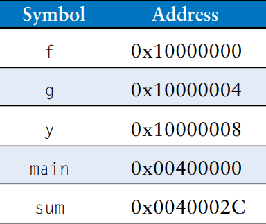
The assembler turns the assembly language code into an object file containing machine language code. The assembler makes two passes through the assembly code. On the first pass, the assembler assigns instruction addresses and finds all the symbols, such as labels and global variable names. The code after the first assembler pass is shown here.
main:
0x00400000 addi $sp, $sp, 4
0x00400004 sw $ra, 0($sp)
0x00400008 addi $a0, $0, 2
0x0040000C sw $a0, f
0x00400010 addi $a1, $0, 3
0x00400014 sw $a1, g
0x00400018 jal sum
0x0040001C sw $v0, y
0x00400020 lw $ra, 0($sp)
0x00400024 addi $sp, $sp, 4
0x00400028 jr $ra
sum:
0x0040002C add $v0, $a0, $a1
0x00400030 jr $ra
The names and addresses of the symbols are kept in a symbol table, as shown in the table for this code. The symbol addresses are filled in after the first pass, when the addresses of labels are known. Global variables are assigned storage locations in the global data segment of memory, starting at memory address 0x10000000.
On the second pass through the code, the assembler produces the machine language code. Addresses for the global variables and labels are taken from the symbol table. The machine language code and symbol table are stored in the object file.
Step 3: Linking
Most large programs contain more than one file. If the programmer changes only one of the files, it would be wasteful to recompile and reassemble the other files. In particular, programs often call procedures in library files; these library files almost never change. If a file of high-level code is not changed, the associated object file need not be updated.
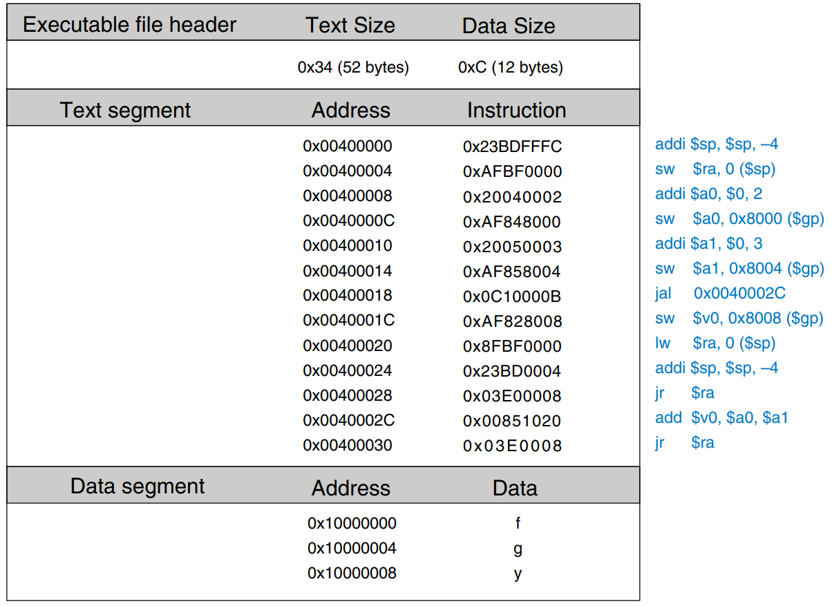
The job of the linker is to combine all of the object files into one machine language file called the executable. The linker relocates the data and instructions in the object file so that they are not all on top of each other. It uses the information in the symbol tables to adjust the addresses of global variables and of labels that are relocated.
In our example, there is only one object file, so no relocation is necessary. The figure shows the executable file. It has three sections: the executable file header, the text segment, and the data segment. The executable file header reports the text size (code size) and data size (amount of globally declared data). Both are given in units of bytes. The text segment gives the instructions and the addresses where they are to be stored. The figure shows the instructions in human-readable format net to the machine code for ease of interpretation, but the executable file includes only machine instructions. The data segment gives the address of each global variable. The global variables are addressed with respect to the base address given by the global pointer, $gp.
Step 4: Loading
The operating system loads a program by reading the text segment of the executable file from a storage device into the text segment of memory. The operating system sets $gp to 0x10008000 (the middle of the global data segment) and $sp to 0x7FFFFFFC (the top of the dynamic data segment), then performs a jal 0x00400000 to jump to the beginning of the program. The figure shows the memory map at the beginning of program execution.
